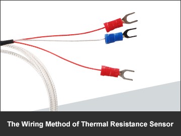
The Wiring Method of Thermal Resistance Sensor
When it comes to the use and advantages of thermal resistance sensor, many people can give their own ideas and suggestions on products. Compared with the way the thermal resistance is wired, some people are at a loss. It's not that you're unfamiliar with the product, but it's easy to overlook the most important parts.
There are three main wiring methods for thermal resistance sensor. Different wiring methods are used in different environments. However, as far as the current situation is concerned, thermal resistance is often used in low temperature environment measurement, such as: boiler, chimney pipe and electric heating plant.
I'm sure you're familiar with the two-wire system of thermal resistance sensor. This kind of wiring method is very simple, but because the connecting wire must have wiring resistance, the size of the wiring resistance is related to the material of the wire, so this method is only suitable for the low-precision measurement environment.
The three-wire system of thermal resistance sensor is the most commonly used wiring method at present. It is wired by connecting one lead at one end of the thermal resistance root and two leads at the other end. However, this method is usually used in conjunction with the bridge, which can better eliminate the influence of lead resistance.
The method of connecting two wires at each end of the thermal resistance sensor root is called four-wire system. Two of the leads provide a constant current for the thermal resistance, convert it into a voltage signal, and then lead it to the instrument through the other two leads. It can be seen that this lead connection mode can completely eliminate the influence of the resistance of the lead. Therefore, it is mainly used for high-precision temperature detection.
Through the above analysis of the wiring method of the thermal resistance sensor, we can accurately choose the high-precision thermal resistance through different connection modes.


