Installation Notices of Turbine Flow Meters
Let’s learn about a flow measuring device called a turbine flow meter. It can be used to measure both liquids and gases, and very common in water treatment, petroleum, chemical, metallurgy, city gas pipeline network and so on.
Lean how to correctly install the turbine flow meters, we will benefit from this.
Installation position of turbine flow meter
1. The installation position should be within the ambient temperature range of -25~55℃, and the humidity should be 80%RH;
2. Install at a place where ventilation is good, away from sun and rain;
3. Away from pipelines with vibration or stress;
4. Avoid places susceptible to strong thermal radiation and radioactivity;
5. Avoid interference of strong external electromagnetic fields to the detection signal. If it cannot be avoided, measures should be taken, such as adding shielding caps to the amplifier of the flow meter (sensor) to eliminate interference.
6. Explosion-proof amplifiers should be used in places with explosion-proof requirements.
7. The installation location should be considered to facilitate installation, operation and maintenance.

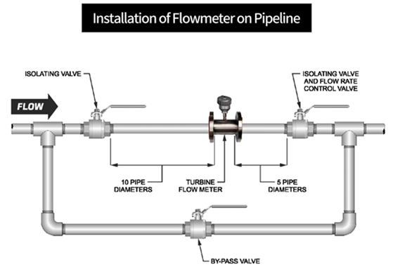
In order to ensure measurement accuracy, install turbine flow meters horizontally on a horizontal pipe, and the direction of the arrow indicated on the flow meter should be consistent with the liquid flow direction. If it must be installed vertically, the liquid should flow upwards from the bottom to ensure that the body of the flow sensor is filled with liquid.
Pipeline requirements
1. In order to eliminate the influence of uneven flow velocity distribution in the pipeline on the measurement accuracy, the flow sensor should have a certain straight pipe section upstream and downstream, or install a rectifier to replace part of the straight pipe section. Usually, the upstream straight pipe section is not less than 15D, and the downstream straight pipe section is not less than 5D (D is the nominal diameter of the flow sensor).
2. In order to eliminate the influence of back flow, uneven flow velocity distribution and swirl flow, a rectifier can be installed upstream. At this time, the straight pipe length of the upstream portion of the flow sensor may be 10D.
3. When the measured liquid contains solid impurities, a filter should be installed upstream of the flow sensor. The mesh number of the filter is 20-60 mesh (3-9 mesh/cm2). Generally, the smaller the diameter of the flow sensor, the larger it is.


