
How to Select, Install, Calibrate, and Maintain Electromagnetic Flowmeters: A Complete Industrial Guide
How Do Electromagnetic Flowmeters Work?
Electromagnetic flowmeters operate based on Faraday’s law of electromagnetic induction, which states that when a conductive fluid passes through a magnetic field, an electrical voltage is generated proportional to the flow velocity.
Before selecting a flowmeter, it’s crucial to understand its principle. Learn more about here here (Wikipedia).
Key components include:
Electrodes – detect induced voltage from fluid movement.
Liner – insulates the flow tube and protects against corrosion.
Transmitter – converts the electrical signal into a flow value.
Housing and flanges – protect and connect the internal components.
How to Choose the Right Electromagnetic Flowmeter?
What factors should be considered when selecting an electromagnetic type flowmeter?
Selecting the wrong flowmeter can cause inaccurate measurements or early failures. Let’s break it down into five main considerations.
Five Key Selection Factors
| Factor | Description | Recommended Practice |
|---|---|---|
| Material Compatibility | Ensure the liner and electrode materials are suitable for the liquid. | Example: for wastewater: rubber + stainless steel; for corrosive chemicals: PTFE + Hastelloy. |
| Flow Range & Velocity | Verify that the meter covers the expected minimum and maximum flow rates. | The flow range and velocity are within the specified for stable readings. |
| Pipe Size | Match the flowmeter size with your pipeline diameter. | Use reducers if necessary but maintain adequate straight pipe length. |
| Environmental Conditions | Check temperature, humidity, and explosion-proof needs. | Example: Use IP68-rated sensors for submersible or outdoor installations. |
| Accuracy & Output Requirements | Higher accuracy means higher cost—choose based on your process tolerance. | For billing/trade, select ±0.2% accuracy; for process control, ±0.5% is sufficient. |
| Type & Function | Select the required types and functions. | Select a split type for submersible or outdoor applications. Inserted type is more suitable for large DN pipes or no pipe cut-off |
Most importantly, it should be noted that generally the conductivity of the medium to be measured is greater than 5 μS/cm (or depending on the manufacturer).
If your medium is city sewage, choose rubber-lined, stainless steel electrode meters.
For corrosive fluids like acids, select PTFE liners with Hastelloy electrodes.
Contact Holykell engineers for detailed corrosion resistance material charts and compatibility lists.
How to Install Electromagnetic Flowmeters?
Improper installation is one of the main causes of inaccurate flow readings. Follow these essential rules.
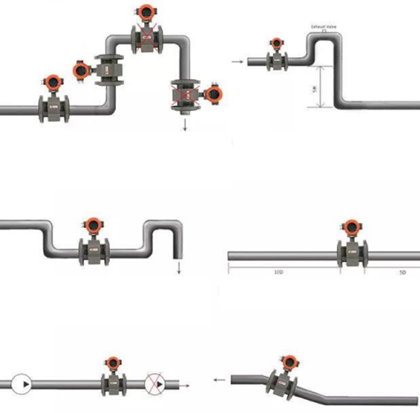
Pipe Orientation:
Install horizontally or vertically (upward flow preferred for slurry or sediment). Ensure the measuring tube is always full of liquid.
Straight Pipe Length:
Maintain ≥10D upstream and ≥5D downstream straight sections (where D = pipe diameter).
Avoid Vibration and Magnetic Interference:
Keep the meter away from large motors, frequency converters, or strong electromagnetic fields.
Grounding Requirements:
Proper grounding ensures measurement stability—details below Section 4..
Converter Installation:
Keep the signal cable between sensor and converter as short as possible, use shielded cable for low conductivity fluids.
If installing on a plastic or coated pipe, use stainless steel grounding rings at both ends of the sensor to ensure the measured medium and the earth share a common zero potential.
How to Ground?
Why is grounding so critical for electromagnetic flowmeters? Because electromagnetic flowmeters measure microvolt-level signals, external interference can easily cause errors.
The induction signal of the magnetic flowmeter itself is very weak and is easily affected by noise. Without a stable ground, noise currents may distort measurements.
Grounding Methods
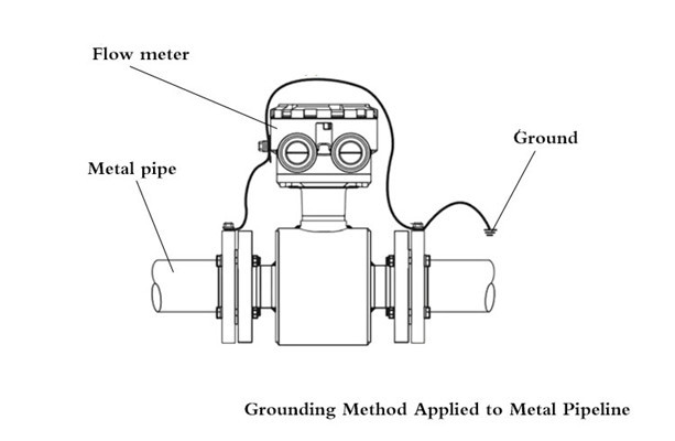
For Metal Pipes
When the electromagnetic flowmeter is installed on a metal pipe (no insulating coating on the inner wall of the metal pipe), connect the metal pipe to the magnetic flowmeter, and then connect the grounding wire to the grounding grid, as shown in Figure 1.
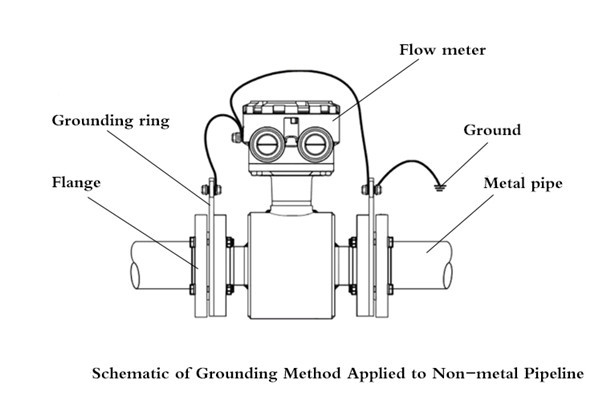
For non-metallic pipes
There are three main grounding methods:
A.Use a grounding ring
Install grounding rings on the flanges at both ends of the lined measuring tube. The purpose is to reliably and stably connect the conductive liquid as the reference point of the differential potential signal to the converter. The signals are connected to form a similar or approximately equal potential to the liquid. The ground ring material is generally the same or similar to the electrode material to ensure corrosion resistance.
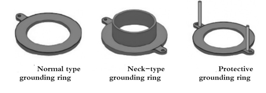
There are three main types of grounding rings: normal type, neck type and protective type. Generally, we use normal grounding rings; protective types are fixed on the flange to protect the flange surface lining from damage; if the medium is highly abrasive, neck type of protective grounding rings should be used.
B.Use grounding electrodes (three electrodes)
When measuring highly corrosive media, the electrode materials of magnetic flowmeters often use precious metals such as tantalum, titanium, and platinum. Since the material of the ground ring is generally required to be the same as the electrode, it is not suitable to add a ground ring for such flow meters, especially for large diameters, the cost is too high. Therefore, in order to save costs, magnetic flowmeters generally use a three-electrode method for grounding, that is, at the lowest point where the sensor measurement tube is perpendicular to the measurement electrode, an additional electrode (the same material and size as the measurement electrode) is added to achieve a grounding effect.
C.Virtual grounding
With the development of technology, a new grounding technology, virtual grounding, has been applied to magflow meters in recent years. By providing isolation of the flow converter input amplifier and the optocoupler in the circuit, the measurement circuit is allowed to float at the potential of the liquid, and the flow rate of the conductive liquid produces an induced voltage only when flowing through the flow sensor. This special processing of the converter signal allows the flowmeter sensor to be grounded for normal operation, reducing installation and eliminating the cost of additional grounding rings or third electrodes.
Precautions
The magnetic flowmeter must be grounded separately, because if it is grounded together with other instruments or electrical devices, the leakage current in the grounding wire will cause series-mode interference to the measurement signal. In severe cases, the flowmeter will not work.
The grounding point should be far away from large electrical appliances to prevent ground current from flowing into the flow meter and causing interference sources.
Never damage the electrodes and rubber lining inside the flow meter when welding.
D.When installing the flow meter, rubber gaskets should be added between flanges to prevent water leakage.
How to Calibrate Magnetic Flowmeters?
Even the best magnetic flowmeters may drift over time due to aging components, chemical corrosion, or surface buildup. Calibration ensures long-term accuracy and compliance with
Preparation and Setup
Before calibration begins, it’s essential to prepare thoroughly:
Selecting Appropriate Equipment: Choose a pump that matches the pipeline diameter and required flow rates for verification testing.
Preheating: Once the flowmeter is installed, ensure it is powered on and allowed to preheat for at least 30 minutes according to calibration specifications.
Initial Setup
Filling with Calibration Medium: Prior to calibration, ensure the flowmeter’s sensor is filled with the calibration medium. Close downstream valves and perform zero adjustment.
Checking Overflow Signals: If using a high-level water tank, verify there are no overflow signals from the surge tank. Circulate the calibration medium within the pipeline system as per specifications, checking for leaks at all seal points.
Calibration Process
Gradual Opening of Valves: Open the valves in sequence—first the front valves, followed by slowly opening the valves at the rear of the flowmeter—to adjust the flow rate at calibration points.
Maintaining Stability: During calibration, adhere to flow measurement regulations. Ensure flow stability at each calibration point: within 1%-2% for volumetric flow method and up to 5% for totalizer method. Monitor temperature fluctuations of the calibration medium, keeping them within 1°C during identification and no more than 5°C throughout the entire process.
Post-Calibration Procedures
After completing calibration, close front valves first, followed by shutting down the pump to prevent damage to pressure stabilization devices. Drain any remaining calibration medium from the testing pipeline and subsequently shut down control systems and air compressors.
Besides, schedule periodic recalibrations as recommended by the manufacturer and take into account ambient temperature and fluid properties. Moreover, conduct training and maintain detailed records of all calibration procedures and results for compliance and reference.
How to Maintain Magnetic Flowmeters?
Maintenance and Common Troubleshooting Tips
| Problem | Possible Cause | Recommended Solution |
|---|---|---|
| Unstable reading | Air bubbles or low flow velocity | Install air release valves; maintain minimum velocity. |
| Zero drift | Deposits on electrodes | Clean periodically with non-abrasive detergent. |
| No signal | Grounding failure or damaged cable | Check grounding resistance; replace cable if corroded. |
| Inconsistent data | Temperature fluctuation | Maintain stable process temperature (±5°C max). |
Routine maintenance should include:
Monthly inspection of grounding and cabling.
Quarterly cleaning of electrodes and liner.
Annual recalibration following ISO/IEC 17025 certified standards.
FAQs About Electromagnetic Flowmeters
Q1: Can magnetic flowmeters measure non-conductive liquids?
No. The liquid must be electrically conductive (typically > 5 μS/cm).
Q2: What is the difference between inline and insertion-type meters?
Inline meters offer higher accuracy; insertion types are easier to install and maintain in large pipelines.
Q3: How often should I calibrate a magflow meter?
Typically every 12–24 months, depending on usage conditions and regulatory requirements.
Q4: Will bubbles in the liquid affect its measurement?
We have detail discussion here.
Conclusion
Selecting, installing, calibrating, and maintaining an electromagnetic flowmeter is not just about buying a sensor — it’s about ensuring long-term measurement reliability. By following best practices in material selection, proper grounding, precise calibration, and regular maintenance, industries can achieve high accuracy and extended service life.
Whether in water treatment, chemical processing, or municipal drainage, the right magflow solution guarantees operational efficiency and compliance with international standards.
Written by Holykell Engineering Team | Verified by Product R&D Department
Last Updated on Nov. 3, 2025